

Functional Dimensioning
How to Use GD&T for CNC Machined Parts
Use GD&T to control function through clear datums, feature relationships and allowable variation. Do not add symbols to make a drawing look precise. Every control should answer what feature matters, relative to which datum, within what zone and how it will be verified.
Start With the Datum Reference Frame
- Select the primary surface that stabilizes the part in assembly.
- Select a secondary feature that controls rotation or lateral location.
- Select a tertiary feature that completes location.
- Confirm the features can be manufactured and measured.
- Use the same functional logic for mating parts where possible.
Common Controls and Uses
| Control | Typical use | Common mistake |
|---|---|---|
| Position | Hole or feature pattern relative to datums | Adding ± coordinate tolerances that conflict |
| Flatness | Single surface form without datum | Using it to control orientation to another face |
| Parallelism/perpendicularity | Orientation relative to datum | Ignoring surface form and datum quality |
| Profile | Complex surface or boundary | Applying a tight all-over profile without function |
| Runout | Rotational surface relative to axis | Unclear datum axis or setup |
Material Condition Modifiers
MMC/LMC can provide functional tolerance and bonus tolerance for features of size, but only when the designer and inspector understand the virtual condition. Do not use modifiers without a clear assembly/gauging purpose.
Measurement Must Be Feasible
A profile or position tolerance may require CMM programming, fixtures and datum simulation. Very small, flexible or hidden features may not support the intended method. Agree on inspection before production.
Avoid Conflicting Requirements
Do not duplicate controls with coordinate dimensions, apply flatness to an axis, reference unstable cosmetic surfaces as datums or overconstrain the same feature through multiple incompatible frames.
Our Review Method for How to Use GD&T for CNC Machined Parts Requirements
A useful supplier solution for How to Use GD&T for CNC Machined Parts starts when ambiguous datums or blanket tight tolerances make machining and inspection plans disagree. Because the buyer can pay for unnecessary precision yet still receive results that do not predict fit, seal or motion, our project review maps each critical characteristic to a manufacturable datum scheme, process stage and accessible measurement method with suitable uncertainty. That approach helps the buyer avoid paying for the wrong process and lowers the chance of discovering a critical issue after machining or finishing.
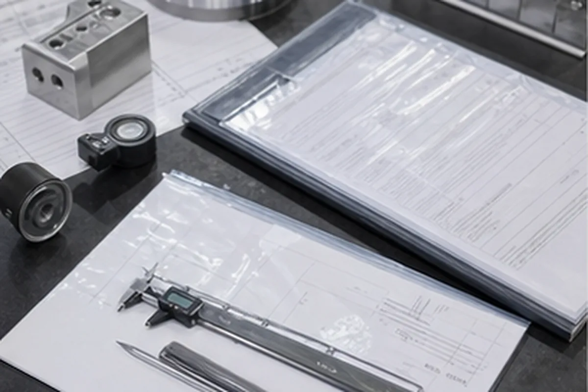
For the How to Use GD&T for CNC Machined Parts buying decision, our review needs the controlled 2D drawing, datum sequence, functional interfaces, tolerance standard, measurement condition and required report. We record assumptions, approval points and evidence requirements before the quotation becomes the production baseline.
Apply Use GD&T for CNC Machined Parts to the Buyer Decision
For Use GD&T for CNC Machined Parts, use the controlling 2D drawing and 3D model to define part number and revision, material and condition, quantity and annual demand, critical tolerances and GD&T, roughness, heat treatment, surface finish, inspection documents, packaging, delivery address and target date. Identify confidentiality restrictions and which DFM changes may be considered for this part.
Price and lead time can be confirmed only after geometry, material availability, programming, workholding, external processes, inspection effort, first-article approval and logistics are reviewed together.
Check the complete RFQ inputs before supplier comparison.