

Hole Location Troubleshooting
CNC Hole Position Errors: Causes, Inspection and Corrective Action
CNC hole position errors usually come from datum interpretation, setup transfer, workholding movement, tool deflection, program or offset errors, or inconsistent measurement alignment. Before correcting the machine, confirm whether the drawing uses coordinate tolerances or true position, whether material condition modifiers apply, and how the inspection datum reference frame was established.
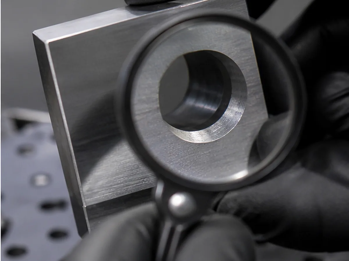
First Identify the Failure Pattern
| Pattern | Possible cause | Diagnostic evidence |
|---|---|---|
| Entire pattern shifted | Work offset or datum origin error | Actual coordinate map |
| Pattern rotated | Part alignment or fixture orientation | Results relative to primary/secondary datums |
| One hole displaced | Program point, drill walk or local surface condition | Program review and entry geometry |
| Error grows across pattern | Scale, thermal or coordinate error | Position trend by location |
| Cross-setup features disagree | Datum transfer or re-clamping stack-up | Setup and probing sequence |
| Buyer and supplier results differ | Datum simulation or bonus tolerance interpretation | Matched CMM alignment and report |
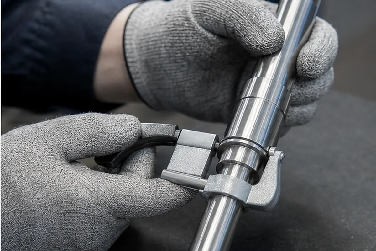
Do Not Confuse Hole Size With Hole Position
A hole can meet diameter but fail location, or fail diameter while its axis is correctly located. With true position at maximum material condition, allowable positional variation may depend on actual feature size. Reports should show enough information to reproduce the acceptance decision rather than only a green pass indicator.
Machining Factors
- Angled or rough entry surfaces causing drill walk
- Long, small-diameter tools deflecting
- Fixture movement or chips under locating surfaces
- Incorrect work coordinate, probing or program revision
- Machining related holes in separate setups
- Thermal movement across large parts
- Deburring or finishing changing the measurable edge
Design and Drawing Improvements
- Select datums that represent how the assembly locates.
- Use basic dimensions and position control consistently.
- Define projected tolerance zone when fastener engagement makes it necessary.
- State whether coating is included in hole size and position inspection.
- Provide adequate entry geometry and tool access.
- Identify locating holes separately from clearance holes.
What Buyers Should Request
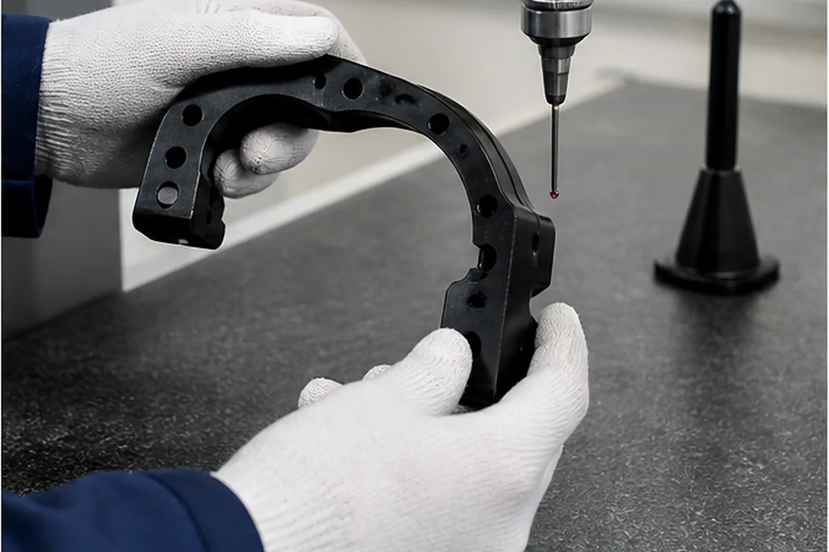
Ask for the ballooned drawing, actual feature sizes, measured position values, datum alignment, material-condition calculation where used, lot traceability and a graphical map of the pattern. For disputed CMM results, exchange the measurement strategy and agree on datum simulation before repeating inspection.
Rework Boundaries
Opening a clearance hole may be possible with design approval, but it changes size and may affect bearing area or edge distance. A locating bore might be corrected by boring, sleeving or another approved repair only when the design authority accepts the method. Do not convert a position failure into an oversized-hole acceptance without documented functional review.
What Our Project Review Resolves Before Quoting CNC Hole Position Errors: Causes, Inspection and Corrective Action
When ambiguous datums or blanket tight tolerances make machining and inspection plans disagree, the buyer can pay for unnecessary precision yet still receive results that do not predict fit, seal or motion. For CNC Hole Position Errors: Causes, Inspection and Corrective Action, our engineering and quotation review maps each critical characteristic to a manufacturable datum scheme, process stage and accessible measurement method with suitable uncertainty. This helps reduce rework, approval delays and avoidable purchasing cost without turning a screening assumption into a capability guarantee.
For the CNC Hole Position Errors: Causes, Inspection and Corrective Action buying decision, we confirm the route only after reviewing the controlled 2D drawing, datum sequence, functional interfaces, tolerance standard, measurement condition and required report. Any unresolved item is listed as an RFQ clarification so the buyer can compare scope, evidence, price and lead time on the same basis.