

Hole Design
How to Design Holes and Deep Holes for CNC Machining
Use standard drill sizes, provide tool entry and chip clearance, and avoid unnecessary depth. As depth-to-diameter ratio increases, straightness, size, finish, chip evacuation and tool breakage become harder to control. Deep holes require project review rather than one universal ratio.
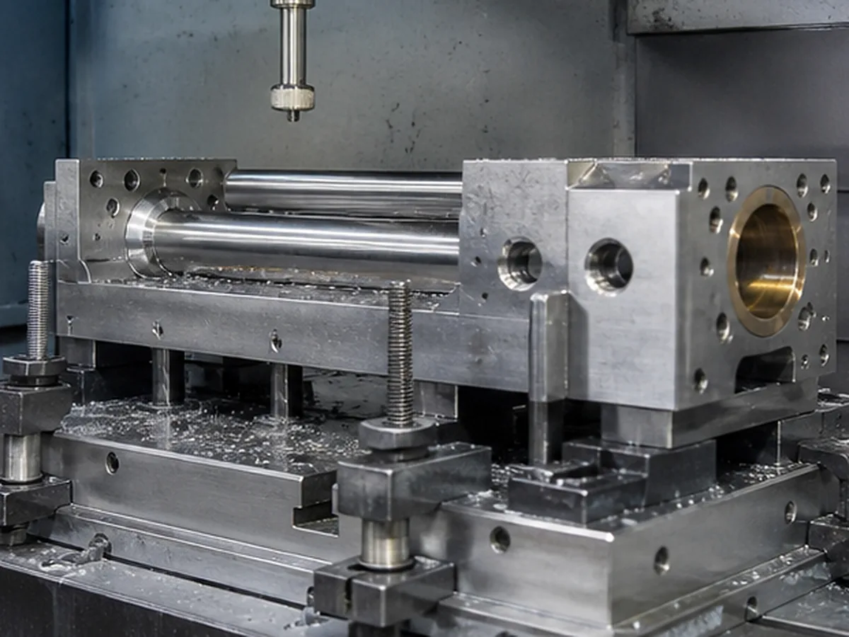
Define the Hole Function
| Hole function | Required information |
|---|---|
| Clearance hole | Fastener size and assembly clearance |
| Locating hole | Fit, datum, position and possible reaming |
| Threaded hole | Thread, depth, class and bottom clearance |
| Fluid passage | Intersection, burr, cleanliness and pressure requirements |
| Bearing/seal bore | Size, form, roughness and alignment |
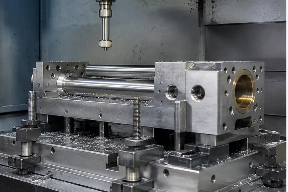
Deep-Hole Risks
- Drill wander and positional error
- Chip packing and tool breakage
- Taper or poor finish
- Difficult coolant delivery
- Inaccessible internal burrs at intersections
- Limited measurement access
Design Improvements
Reduce depth where possible, increase diameter, allow access from both sides, add a breakout or cleaning port, use a through hole instead of blind, and separate a complex passage into an assembly when function permits.
Hole Bottom and Entry
Standard drills create a conical bottom. If usable cylindrical depth matters, dimension it separately. Angled or curved entry surfaces can cause drill walk and may require spot faces or another process.
Inspection and Cleaning
Deep bores may need plug, air, optical, CMM, flow or specialized measurement. Fluid passages require an explicit burr and cleanliness standard; “clean” is not measurable without limits.
From How to Design Holes and Deep Holes for CNC Machining Requirements to a Controlled Manufacturing Plan
A useful supplier solution for How to Design Holes and Deep Holes for CNC Machining starts when deep, narrow or obstructed features restrict tool access, chip removal and measurement. Because tool deflection, trapped burrs or inaccessible characteristics can increase scrap and late design changes, our project review checks depth-to-diameter ratio, corner radius, tool reach, exit or relief space, workholding and in-process measurement access before quoting the feature. That approach helps the buyer avoid paying for the wrong process and lowers the chance of discovering a critical issue after machining or finishing.
For the How to Design Holes and Deep Holes for CNC Machining buying decision, our review needs feature depth, diameter or radius, access direction, blind/through condition, deburring requirement, datum relationship and acceptable DFM change. We record assumptions, approval points and evidence requirements before the quotation becomes the production baseline.
Confirm the Process for Design Holes and Deep Holes for CNC Machining
For Design Holes and Deep Holes for CNC Machining, submit the 2D drawing and 3D model with matching revision, exact material and condition, quantity and repeat demand. Identify relevant datums, critical tolerances, GD&T, threads, difficult-access geometry, thin walls, roughness, heat treatment and finish requirements.
The route for Design Holes and Deep Holes for CNC Machining may require multiple setups, dedicated workholding, intermediate inspection or a justified secondary process. Select grinding, EDM, stress relief or post-finish verification only when the geometry and function require it; machine axis count alone does not establish final capability.