

Machining Problem Analysis
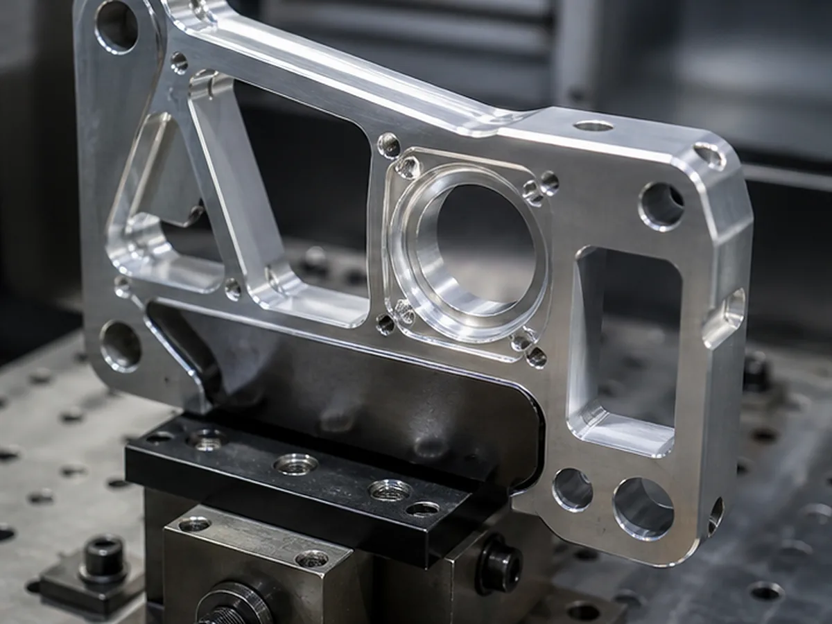
Why Thin-Wall CNC Parts Deform—and How to Reduce the Risk
Thin-wall CNC parts deform mainly because cutting force, clamping pressure, heat and residual material stress act on a structure with low stiffness. The part may look correct while clamped and move after release. Risk is reduced by improving geometry, stock condition, roughing sequence, workholding, toolpath and inspection method together—not by changing one parameter in isolation.
First Determine When the Movement Appears
| Observation | Likely mechanism | What to investigate |
|---|---|---|
| Correct in fixture, wrong after release | Clamping distortion or released stress | Jaw force, support points, roughing balance |
| Wall vibrates during cutting | Insufficient stiffness or poor tool engagement | Tool overhang, stepdown, wall support, cutting direction |
| Part bows after heavy stock removal | Uneven residual-stress release | Stock form, material condition, symmetric roughing |
| Dimensions drift during a cycle | Thermal growth | Coolant, cutting heat, machine and part stabilization |
| Inspection results disagree | Flexible-part measurement variation | Fixturing, probe force, support and temperature |
Design Changes With the Highest Leverage
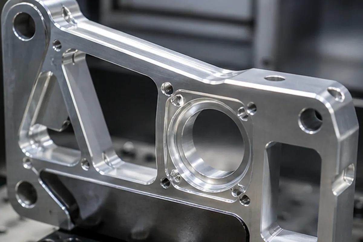
- Increase wall thickness or add ribs where stiffness matters.
- Use generous internal radii to reduce tool load and improve access.
- Avoid abrupt thickness transitions that concentrate stress.
- Keep temporary support tabs or sacrificial stock when removal can occur late.
- Define free-state inspection if the part must be accepted without assembly restraint.
The right solution depends on mass, span, alloy, tolerance, finish and assembly constraint. A wall-thickness rule without those conditions is unreliable.
Process Controls for a Fixed Design
- Choose stable stock: material form and temper can affect residual stress.
- Rough in balanced stages: remove material progressively from opposing regions where geometry permits.
- Allow stress redistribution: use an intermediate rest or stabilization step when justified.
- Use low-distortion workholding: spread force and support the part near cutting loads.
- Leave finish allowance: finish critical surfaces after major stress has been released.
- Control tool engagement: sharp tools, limited radial load and short overhang reduce wall deflection.
- Inspect consistently: define support, temperature and clamped/free-state conditions.
A Common Failure in Supplier Communication
The drawing may specify flatness on a thin free wall but not explain whether the part is inspected unrestrained, lightly supported or assembled to a rigid frame. Each condition can produce a different result. State the functional condition and do not ask the supplier to infer it from the CAD model.
Information Needed for a Useful DFM Review
- 3D model and controlled drawing
- Material alloy, temper and permitted stock form
- Critical wall thickness, span and datum scheme
- Free-state or restrained inspection condition
- Surface finish or heat-treatment sequence
- Mating component and assembly preload, if relevant
- Prototype quantity and expected production volume
How We Reduce Sourcing and Manufacturing Risk for Why Thin-Wall CNC Parts Deform—and How to Reduce the Risk
The purchasing issue behind Why Thin-Wall CNC Parts Deform—and How to Reduce the Risk is that thin or flexible geometry can move during clamping, stock removal, heat treatment or measurement; as a result, a part may pass while restrained and fail after release or during assembly. Our response is to reviews stock condition, support points, cutting sequence, datum transfer and the free-state or restrained inspection condition before fixing the route. The objective is to protect assembly and validation schedules while reducing preventable scrap, rework and supplier-change risk.
For the Why Thin-Wall CNC Parts Deform—and How to Reduce the Risk buying decision, before we confirm price or delivery, the buyer should send wall height and span, material condition, datums, functional tolerance, assembly support, finish sequence and measurement condition. If a requirement cannot yet be verified, we keep it as an open condition instead of presenting it as a guaranteed result.
Apply Thin-Wall CNC Parts Deform—and How to Reduce the Risk to the Buyer Decision
For Thin-Wall CNC Parts Deform—and How to Reduce the Risk, use the controlling 2D drawing and 3D model to define part number and revision, material and condition, quantity and annual demand, critical tolerances and GD&T, roughness, heat treatment, surface finish, inspection documents, packaging, delivery address and target date. Identify confidentiality restrictions and which DFM changes may be considered for this part.
Price and lead time can be confirmed only after geometry, material availability, programming, workholding, external processes, inspection effort, first-article approval and logistics are reviewed together.
Check the complete RFQ inputs before supplier comparison.