

GD&T Position
True Position Tolerance for CNC Machined Parts
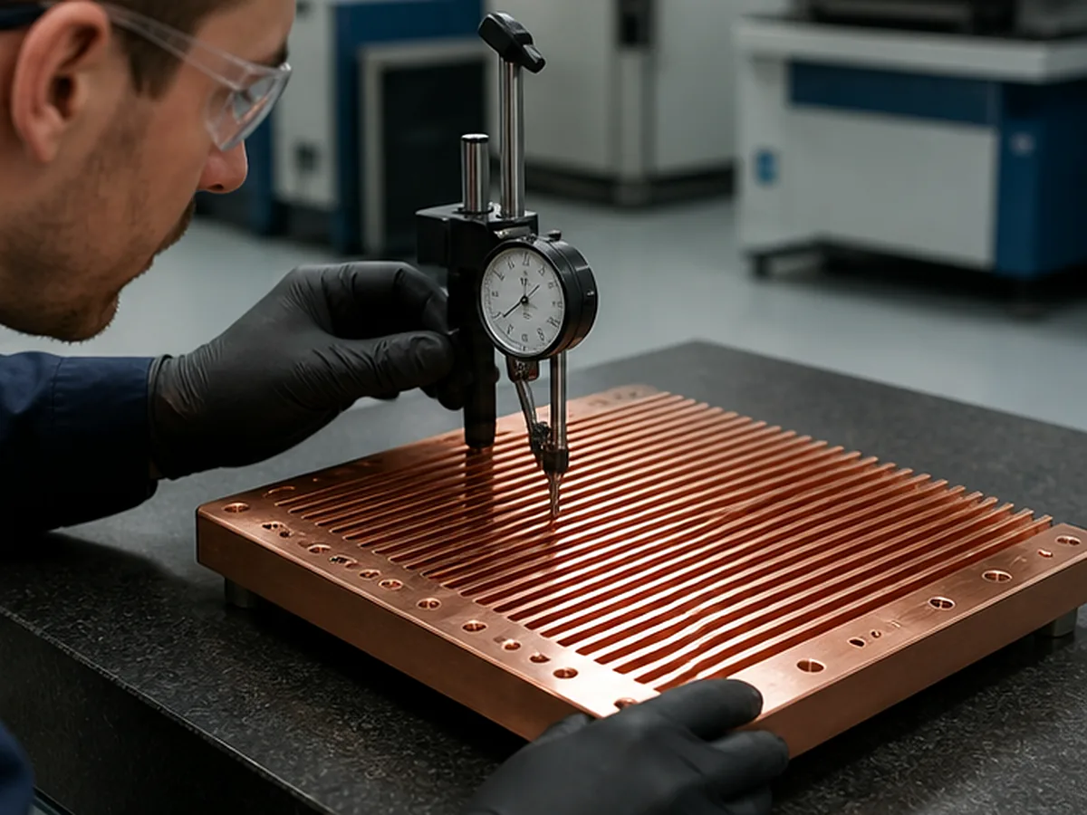
True position controls the location of a feature’s axis, center plane or derived element relative to basic dimensions and stated datums. To evaluate it correctly, confirm the tolerance-zone shape, datum reference frame, material-condition modifiers and actual feature size. Hole size and position are separate requirements.
Recommended Engineering Method
- Define the feature size and its size limits.
- Locate it with basic dimensions.
- Apply position to the correct feature and datum sequence.
- State MMC, LMC or RFS conditions as required by the governing standard.
- Plan a measurement method that reproduces datum simulation.
Common Specification and Inspection Errors
- Using plus/minus coordinates and position redundantly
- Ignoring bonus tolerance at MMC
- Reporting pass/fail without actual size and position
- Inspecting from a convenient origin instead of the datum frame
Questions the Buyer and Supplier Must Resolve
- Is the functional requirement assembly clearance or precise location?
- Does the mating condition justify MMC?
- Are datums valid and accessible?
- Can CMM or functional gauging evaluate the requirement?
Required Evidence
Use the controlled drawing, actual-value results, stated equipment/method, datum or support setup, inspection condition and approval record. The appropriate method and achievable uncertainty remain feature- and project-specific.
Acceptance Boundary
Formexi can review manufacturability and inspection feasibility, but the buyer retains design authority for functional requirements and deviations. Any GD&T interpretation must follow the standard edition stated on the drawing.
From True Position Tolerance for CNC Machined Parts Requirements to a Controlled Manufacturing Plan
A useful supplier solution for True Position Tolerance for CNC Machined Parts starts when ambiguous datums or blanket tight tolerances make machining and inspection plans disagree. Because the buyer can pay for unnecessary precision yet still receive results that do not predict fit, seal or motion, our project review maps each critical characteristic to a manufacturable datum scheme, process stage and accessible measurement method with suitable uncertainty. That approach helps the buyer avoid paying for the wrong process and lowers the chance of discovering a critical issue after machining or finishing.
For the True Position Tolerance for CNC Machined Parts buying decision, our review needs the controlled 2D drawing, datum sequence, functional interfaces, tolerance standard, measurement condition and required report. We record assumptions, approval points and evidence requirements before the quotation becomes the production baseline.
Apply True Position Tolerance for CNC Machined Parts to the Buyer Decision
For True Position Tolerance for CNC Machined Parts, use the controlling 2D drawing and 3D model to define part number and revision, material and condition, quantity and annual demand, critical tolerances and GD&T, roughness, heat treatment, surface finish, inspection documents, packaging, delivery address and target date. Identify confidentiality restrictions and which DFM changes may be considered for this part.
Price and lead time can be confirmed only after geometry, material availability, programming, workholding, external processes, inspection effort, first-article approval and logistics are reviewed together.
Check the complete RFQ inputs before supplier comparison.