

Design for Stability
How to Design Thin-Wall CNC Machined Parts
Use wall height, unsupported span, ribs, material condition, clamping access and functional tolerance to design thin-wall CNC machined parts. A nominal wall value cannot prove feasibility: the complete geometry, stock-removal balance, released-part condition and inspection method must be reviewed together.
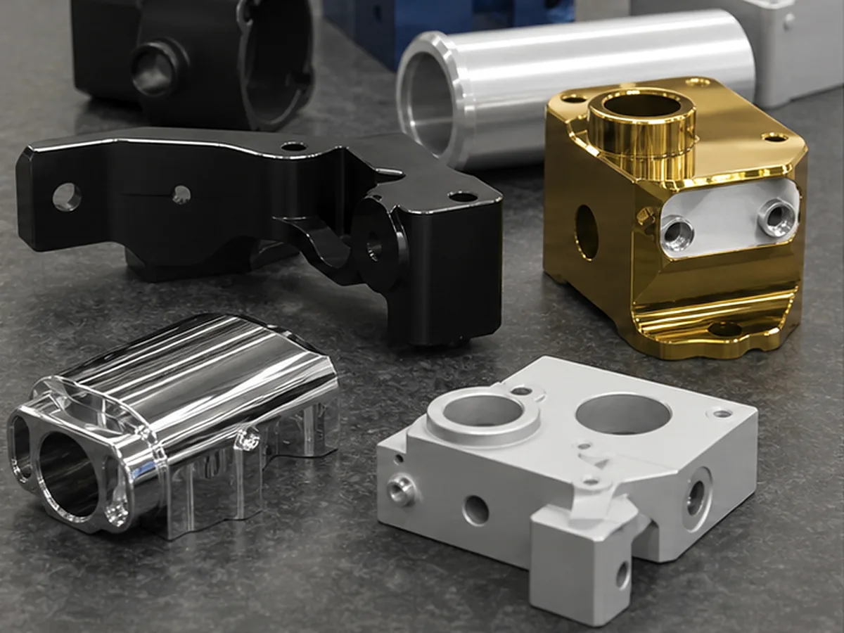
Design Features That Improve Stability
- Shorten unsupported wall height and span.
- Add ribs or local thickness near mounting points.
- Use smooth thickness transitions.
- Keep opposing walls and material removal balanced.
- Avoid tight flatness on flexible cosmetic panels.
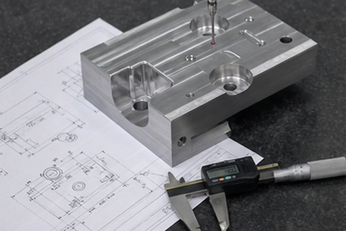
- Define measurement in free or assembled condition.
Material Behavior
| Material direction | Typical concern |
|---|---|
| Aluminum | Residual stress release after large pocketing |
| Stainless/steel | Cutting force, heat and stock condition |
| POM/nylon | Clamping, temperature and moisture change |
| PEEK/filled plastics | Cost, internal stress and directional behavior |
Manufacturing Support Is Temporary
Temporary ribs, tabs, filler or custom fixtures can stabilize machining, but the released part must still meet function. If it only meets tolerance while clamped, the drawing should define that condition or the design should change.
Finishing Effects
Heat treatment, anodizing, blasting, plating and polishing can move or damage thin features. Plan handling and packaging so parts do not deform after acceptance.
Common Mistake
Reducing every wall to save raw material can increase cycle time, fixtures, inspection and scrap more than the material saving. Preserve thickness where stiffness controls manufacturability.
How We Reduce Sourcing and Manufacturing Risk for How to Design Thin-Wall CNC Machined Parts
A useful supplier solution for How to Design Thin-Wall CNC Machined Parts starts when thin or flexible geometry can move during clamping, stock removal, heat treatment or measurement. Because a part may pass while restrained and fail after release or during assembly, our project review reviews stock condition, support points, cutting sequence, datum transfer and the free-state or restrained inspection condition before fixing the route. That approach helps the buyer avoid paying for the wrong process and lowers the chance of discovering a critical issue after machining or finishing.
For the How to Design Thin-Wall CNC Machined Parts buying decision, our review needs wall height and span, material condition, datums, functional tolerance, assembly support, finish sequence and measurement condition. We record assumptions, approval points and evidence requirements before the quotation becomes the production baseline.
Apply Design Thin-Wall CNC Machined Parts to the Buyer Decision
For Design Thin-Wall CNC Machined Parts, use the controlling 2D drawing and 3D model to define part number and revision, material and condition, quantity and annual demand, critical tolerances and GD&T, roughness, heat treatment, surface finish, inspection documents, packaging, delivery address and target date. Identify confidentiality restrictions and which DFM changes may be considered for this part.
Price and lead time can be confirmed only after geometry, material availability, programming, workholding, external processes, inspection effort, first-article approval and logistics are reviewed together.
Check the complete RFQ inputs before supplier comparison.