

Wall Stability
How to Design Wall Thickness for CNC Machined Parts
Choose wall thickness from material, unsupported height, length, clamping, removed stock and required tolerance. A short supported wall can be much thinner than a tall free wall. The following screening review threshold is approximately 0.5 mm for metal and 0.8 mm for plastic, not a guaranteed minimum.
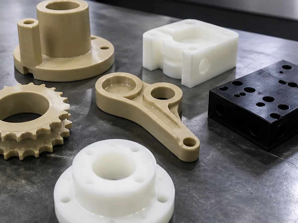
Why Walls Move During Machining
- Cutting force deflects the wall.
- Clamping bends a flexible section.
- Heat expands the material locally.
- Residual stress is released during pocketing.
- Deburring, coating or heat treatment changes the final geometry.
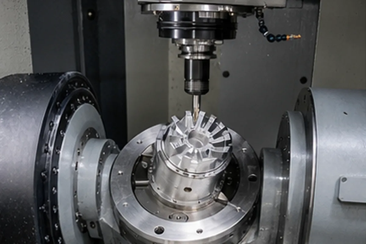
Review Thickness With Geometry
| Geometry | Relative risk |
|---|---|
| Short wall supported by ribs | Lower than the same thickness at large height |
| Tall unsupported wall | High deflection and vibration risk |
| Large flat enclosure panel | Residual stress and flatness risk |
| Thin cylindrical sleeve | Clamping ovality and bore/OD relationship risk |
| Filled plastic wall | Orientation, heat and dimensional recovery risk |
Design Changes That Improve Stability
- Increase thickness only in critical unsupported zones.
- Add ribs, bosses or gradual transitions.
- Reduce deep pocket area where function permits.
- Avoid abrupt thickness changes and isolated heavy sections.
- Relax nonfunctional flatness or profile requirements.
- Define assembly restraint if the part is flexible by design.
Manufacturing Strategies
Balanced roughing, staged finishing, temporary support, soft/distributed clamping, stress-relieved stock and controlled inspection can help. These add process time and cannot always compensate for an unstable design.
Measurement Condition
Specify whether a flexible part is inspected free, clamped or assembled. Without this, supplier and buyer can measure the same part differently and both obtain valid but incompatible results.
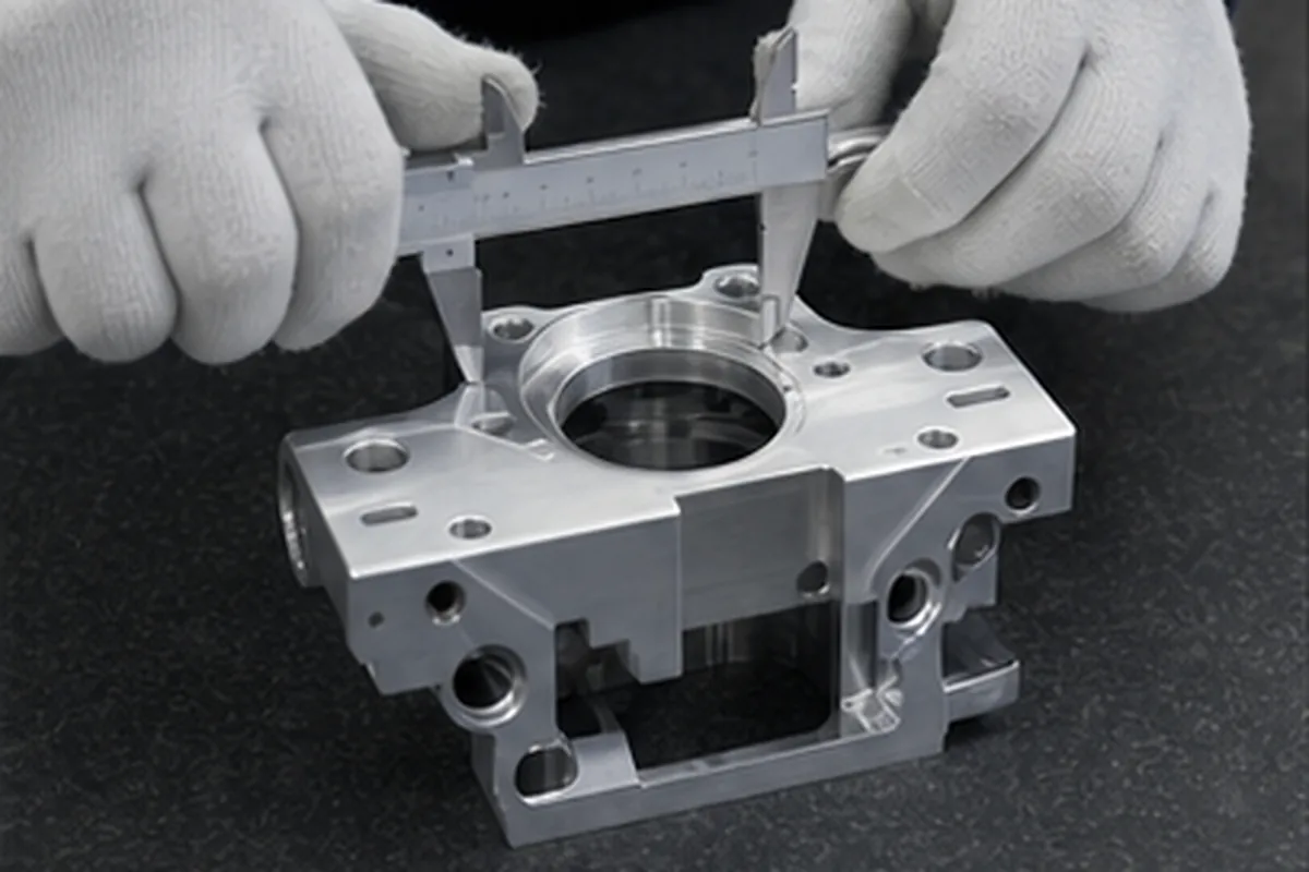
Our Review Method for How to Design Wall Thickness for CNC Machined Parts Requirements
When the buyer needs a supplier response tied to the actual part rather than a generic capability statement, a broad promise can leave geometry, material, quality, cost and delivery assumptions unresolved. For How to Design Wall Thickness for CNC Machined Parts, our engineering and quotation review turns the drawing and purchase requirement into documented process, inspection and approval questions before price or production is confirmed. This helps reduce rework, approval delays and avoidable purchasing cost without turning a screening assumption into a capability guarantee.
For the How to Design Wall Thickness for CNC Machined Parts buying decision, we confirm the route only after reviewing the controlled drawing and model, material, quantities, critical requirements, finish, quality documents, target date, destination and confidentiality needs. Any unresolved item is listed as an RFQ clarification so the buyer can compare scope, evidence, price and lead time on the same basis.
Apply Design Wall Thickness for CNC Machined Parts to the Buyer Decision
For Design Wall Thickness for CNC Machined Parts, use the controlling 2D drawing and 3D model to define part number and revision, material and condition, quantity and annual demand, critical tolerances and GD&T, roughness, heat treatment, surface finish, inspection documents, packaging, delivery address and target date. Identify confidentiality restrictions and which DFM changes may be considered for this part.
Price and lead time can be confirmed only after geometry, material availability, programming, workholding, external processes, inspection effort, first-article approval and logistics are reviewed together.
Check the complete RFQ inputs before supplier comparison.