

Hidden Feature Access
How to Design Undercuts for CNC Machining
Use undercuts only when function requires them and prefer standard tool profiles. Undercuts block direct tool access and may need lollipop, T-slot, dovetail, grooving, EDM or multiple setups. Width, depth, corner radius and access opening determine feasibility.
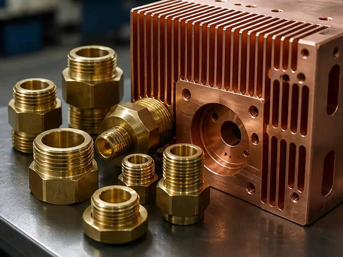
Common Undercut Types
| Type | Typical process | Design concern |
|---|---|---|
| Internal retaining groove | Turning grooving tool | Width, diameter, corner and gauge access |
| T-slot | T-slot cutter | Entry slot, neck clearance and depth |
| Dovetail | Standard-angle dovetail cutter | Angle, neck and inspection |
| Backside milled relief | Lollipop/undercut tool or extra setup | Tool shank and collision clearance |
| Sharp conductive profile | EDM | Material conductivity and access |
Design for Standard Tools
Standard widths and angles reduce special tooling and lead time. Provide enough entry and neck clearance for both cutter head and shank. A tool may fit the cutting feature but collide during entry.
Inspection Access
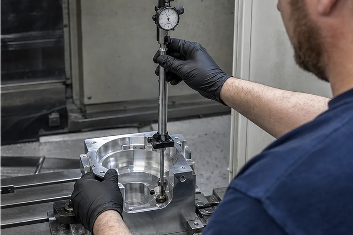
Hidden features can be harder to measure than to cut. Define whether the feature is controlled by functional gauge, optical method, CMM stylus, sectioned sample or another approved method.
Alternatives
Split the part into an assembly, use a through-slot, change the mating component, use a retaining ring standard or eliminate a nonfunctional relief. The cheapest undercut is often the one redesigned out.
Drawing Requirements
Provide a section view with width, depth, radius, angle, datum and entry path. Do not rely on a hidden 3D feature without a controlled 2D callout.
From How to Design Undercuts for CNC Machining Requirements to a Controlled Manufacturing Plan
When deep, narrow or obstructed features restrict tool access, chip removal and measurement, tool deflection, trapped burrs or inaccessible characteristics can increase scrap and late design changes. For How to Design Undercuts for CNC Machining, our engineering and quotation review checks depth-to-diameter ratio, corner radius, tool reach, exit or relief space, workholding and in-process measurement access before quoting the feature. This helps reduce rework, approval delays and avoidable purchasing cost without turning a screening assumption into a capability guarantee.
For the How to Design Undercuts for CNC Machining buying decision, we confirm the route only after reviewing feature depth, diameter or radius, access direction, blind/through condition, deburring requirement, datum relationship and acceptable DFM change. Any unresolved item is listed as an RFQ clarification so the buyer can compare scope, evidence, price and lead time on the same basis.
Confirm the Process for Design Undercuts for CNC Machining
For Design Undercuts for CNC Machining, submit the 2D drawing and 3D model with matching revision, exact material and condition, quantity and repeat demand. Identify relevant datums, critical tolerances, GD&T, threads, difficult-access geometry, thin walls, roughness, heat treatment and finish requirements.
The route for Design Undercuts for CNC Machining may require multiple setups, dedicated workholding, intermediate inspection or a justified secondary process. Select grinding, EDM, stress relief or post-finish verification only when the geometry and function require it; machine axis count alone does not establish final capability.