

Multi-Axis Feature Access
How to Design Parts for 5-Axis CNC Machining
Use 5-axis machining when angled features, compound surfaces or cross-face relationships benefit from changing tool orientation or fewer setups. Do not add complexity merely to justify five axes. Workholding, collision clearance, tool reach and inspection still control feasibility.
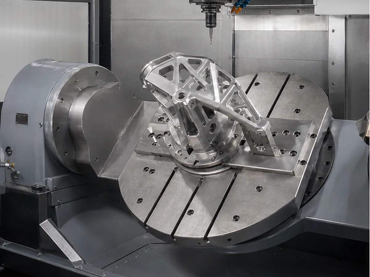
3+2 Versus Simultaneous Motion
| Approach | Use |
|---|---|
| 3+2 positioning | Fixed-angle faces, holes and multi-side features |
| Simultaneous 5-axis | Compound contours and changing tool orientation during cutting |
Choose simultaneous motion only when geometry or surface continuity requires it.
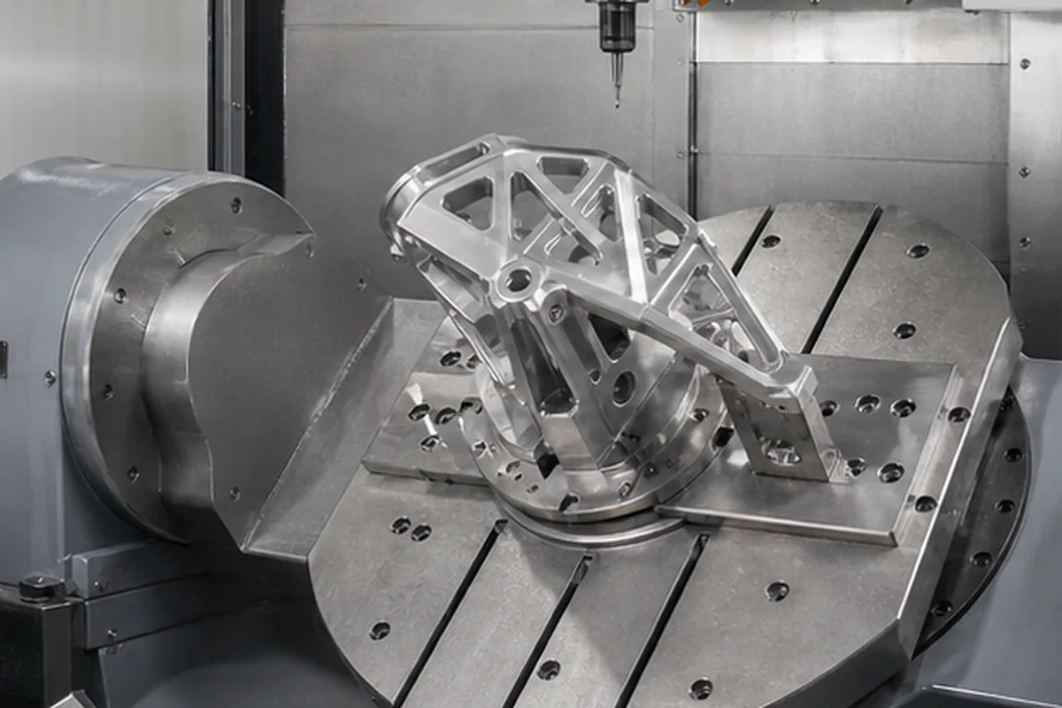
Design for Tool and Holder Clearance
- Provide clearance around inclined features.
- Avoid deep narrow regions that block the holder.
- Use practical corner and fillet radii.
- Leave workholding surfaces or sacrificial stock.
- Consider rotary-axis travel and part orientation.
One Setup Does Not Eliminate All Error
Tool calibration, rotary-center accuracy, thermal behavior, post-processing and workholding still matter. Five axes can improve feature relationships, but it does not guarantee ±0.01 mm across every surface.
Surface and Toolpath Requirements
If surface blending, scallop or tool marks are functional, specify them and provide CAD with suitable surface quality. Cosmetic freeform surfaces may need an approved sample in addition to roughness.
Capability Boundary
Formexi’s specific five-axis machine models, travel and owned-versus-network status remain pending audit. Every project requires equipment and inspection confirmation.
What Our Project Review Resolves Before Quoting How to Design Parts for 5-Axis CNC Machining
A useful supplier solution for How to Design Parts for 5-Axis CNC Machining starts when buyers can overpay or lose datum consistency when a process is chosen from a machine label instead of the part geometry. Because unnecessary setups or an unjustified high-end route can add cost without improving the functional result, our project review compares rotational versus prismatic geometry, feature access, datum relationships, workholding, batch size and measurement access before selecting milling, turning or a combined route. That approach helps the buyer avoid paying for the wrong process and lowers the chance of discovering a critical issue after machining or finishing.
For the How to Design Parts for 5-Axis CNC Machining buying decision, our review needs the 2D drawing and 3D model, overall size, material state, critical datums and tolerances, quantity, finish and inspection documents. We record assumptions, approval points and evidence requirements before the quotation becomes the production baseline.
Confirm the Process for Design Parts for 5-Axis CNC Machining
For Design Parts for 5-Axis CNC Machining, submit the 2D drawing and 3D model with matching revision, exact material and condition, quantity and repeat demand. Identify relevant datums, critical tolerances, GD&T, threads, difficult-access geometry, thin walls, roughness, heat treatment and finish requirements.
The route for Design Parts for 5-Axis CNC Machining may require multiple setups, dedicated workholding, intermediate inspection or a justified secondary process. Select grinding, EDM, stress relief or post-finish verification only when the geometry and function require it; machine axis count alone does not establish final capability.