

Tool Access
How to Design Internal Corner Radii for CNC Milling
Internal milled corners cannot be perfectly sharp because rotating cutters have a radius. Use the largest radius that the part function allows, and make the corner radius larger than the selected tool radius where possible. This improves tool rigidity, finish, cycle time and cost.
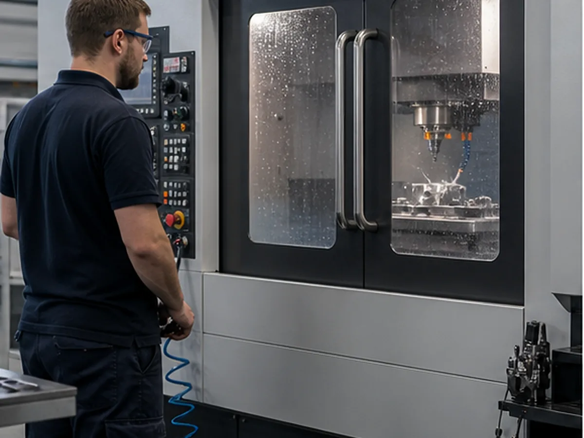
Why Radius Size Changes Cost
A small corner radius requires a smaller cutter. In a deep pocket, that tool becomes long and flexible, increasing vibration, multiple passes and failure risk. A slightly larger radius can allow a much more rigid tool and shorter cycle.
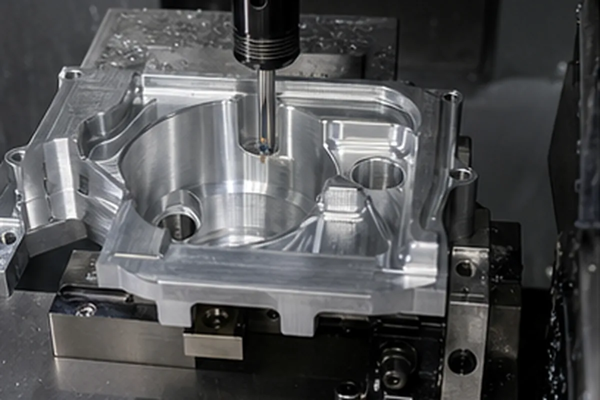
Design Rules
- Use consistent radii where possible to reduce tool changes.
- Make floor radius and vertical corner radius explicit.
- Avoid forcing a cutter to engage 180 degrees in the corner.
- Increase radius as pocket depth increases.
- Use reliefs or dog-bone features when a square mating part must fit.
Sharp Corner Alternatives
| Requirement | Possible solution |
|---|---|
| Square insert must fit | Corner relief/dog-bone or change the mating part |
| Sharp internal conductive profile | Wire or sinker EDM for suitable materials |
| Broached internal shape | Broaching where quantity and geometry justify tooling |
| Nonfunctional visual corner | Accept a milled radius |
Common Drawing Error
Modeling a nominally sharp corner and leaving the supplier to choose any radius can create assembly interference. State the maximum allowed radius or provide relief geometry.
Depth Must Be Reviewed With Radius
The same radius may be easy near the top of a pocket and difficult at depth. Send the complete 3D model so tool length and access can be checked.
Our Review Method for How to Design Internal Corner Radii for CNC Milling Requirements
The purchasing issue behind How to Design Internal Corner Radii for CNC Milling is that deep, narrow or obstructed features restrict tool access, chip removal and measurement; as a result, tool deflection, trapped burrs or inaccessible characteristics can increase scrap and late design changes. Our response is to checks depth-to-diameter ratio, corner radius, tool reach, exit or relief space, workholding and in-process measurement access before quoting the feature. The objective is to protect assembly and validation schedules while reducing preventable scrap, rework and supplier-change risk.
For the How to Design Internal Corner Radii for CNC Milling buying decision, before we confirm price or delivery, the buyer should send feature depth, diameter or radius, access direction, blind/through condition, deburring requirement, datum relationship and acceptable DFM change. If a requirement cannot yet be verified, we keep it as an open condition instead of presenting it as a guaranteed result.
Confirm the Process for Design Internal Corner Radii for CNC Milling
For Design Internal Corner Radii for CNC Milling, submit the 2D drawing and 3D model with matching revision, exact material and condition, quantity and repeat demand. Identify relevant datums, critical tolerances, GD&T, threads, difficult-access geometry, thin walls, roughness, heat treatment and finish requirements.
The route for Design Internal Corner Radii for CNC Milling may require multiple setups, dedicated workholding, intermediate inspection or a justified secondary process. Select grinding, EDM, stress relief or post-finish verification only when the geometry and function require it; machine axis count alone does not establish final capability.