

Tool Reach and Stability
How to Design Deep Pockets and Cavities for CNC Milling
Reduce pocket depth, increase internal radii and provide open tool access whenever function allows. Deep cavities require long tools that deflect and vibrate, increasing cycle time, corner radius, surface variation and risk. Depth must be reviewed with width, material and wall stability.
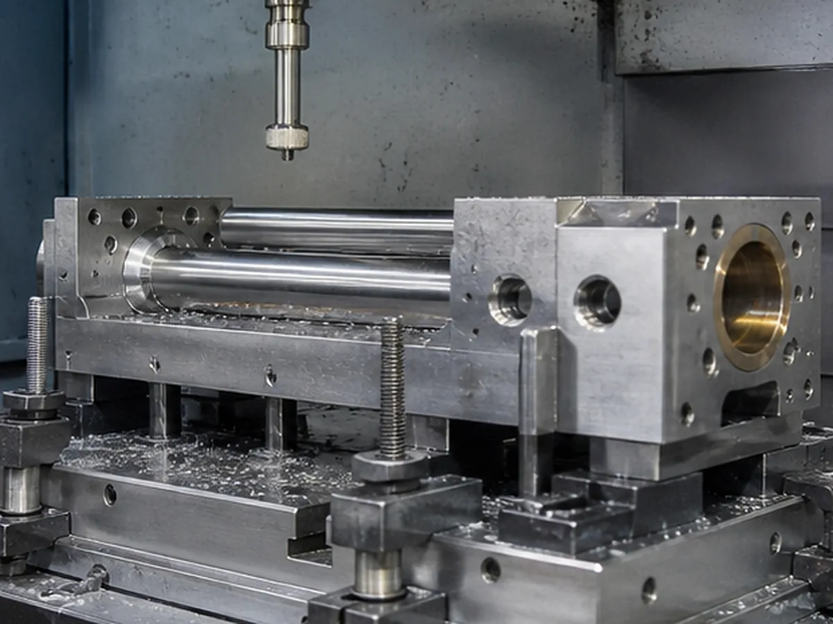
Why Deep Pockets Cost More
- Longer, less rigid tools require lighter cuts.
- Chip evacuation and coolant access become difficult.
- Floor and wall finish vary with tool deflection.
- Small corner radii require even smaller tools.
- Large material removal can distort surrounding walls.
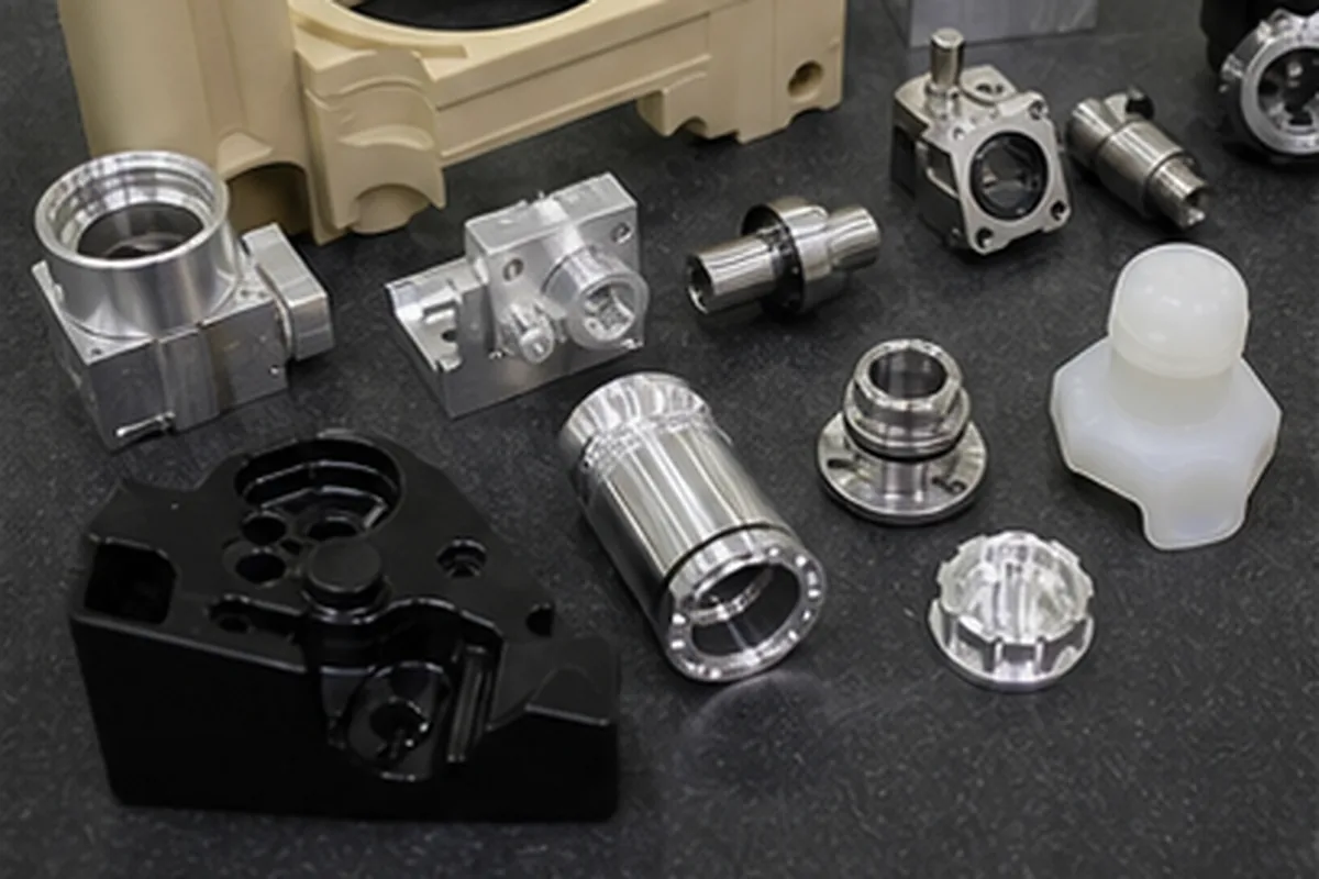
Design Improvements
| Change | Benefit |
|---|---|
| Reduce depth | Shorter, more rigid tool and faster cutting |
| Increase corner radius | Larger cutter and smoother corner engagement |
| Open one side | Improved tool and chip access |
| Use stepped depths | Matches tool reach to functional zones |
| Split into an assembly | Allows direct machining and cleaning |
Floor and Wall Requirements
Specify flatness and roughness only where functional. Deep walls may show tool blending or taper. A fine finish at the bottom may require a separate tool and inspection method.
Multi-Axis Is Not a Universal Cure
Tilting the tool can improve access on some geometry, but machine travel, holder collision and wall depth still apply. A design change may be more reliable and economical than simultaneous five-axis cutting.
Cleaning and Inspection
Deep cavities can trap chips and cleaning media. Define cleanliness and inspection access. Hidden floor dimensions may require CMM stylus or special methods confirmed before production.
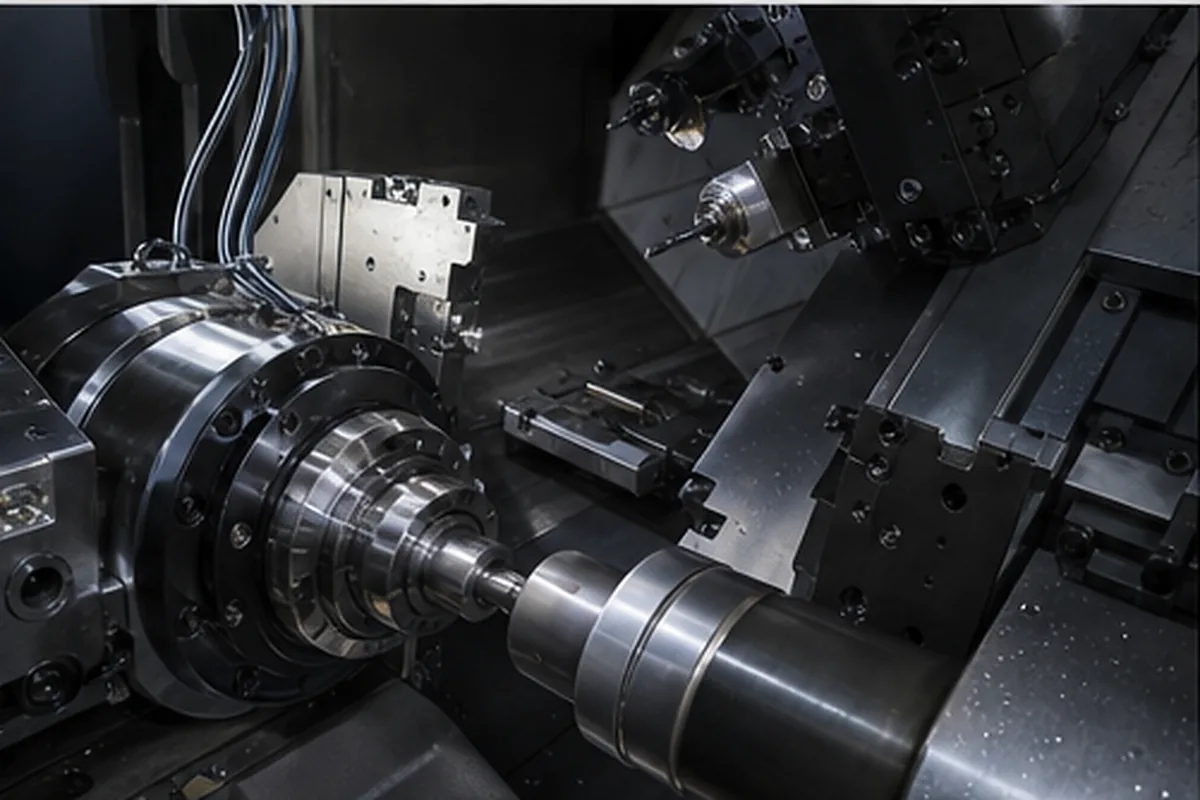
Our Review Method for How to Design Deep Pockets and Cavities for CNC Milling Requirements
The purchasing issue behind How to Design Deep Pockets and Cavities for CNC Milling is that deep, narrow or obstructed features restrict tool access, chip removal and measurement; as a result, tool deflection, trapped burrs or inaccessible characteristics can increase scrap and late design changes. Our response is to checks depth-to-diameter ratio, corner radius, tool reach, exit or relief space, workholding and in-process measurement access before quoting the feature. The objective is to protect assembly and validation schedules while reducing preventable scrap, rework and supplier-change risk.
For the How to Design Deep Pockets and Cavities for CNC Milling buying decision, before we confirm price or delivery, the buyer should send feature depth, diameter or radius, access direction, blind/through condition, deburring requirement, datum relationship and acceptable DFM change. If a requirement cannot yet be verified, we keep it as an open condition instead of presenting it as a guaranteed result.
Confirm the Process for Design Deep Pockets and Cavities for CNC Milling
For Design Deep Pockets and Cavities for CNC Milling, submit the 2D drawing and 3D model with matching revision, exact material and condition, quantity and repeat demand. Identify relevant datums, critical tolerances, GD&T, threads, difficult-access geometry, thin walls, roughness, heat treatment and finish requirements.
The route for Design Deep Pockets and Cavities for CNC Milling may require multiple setups, dedicated workholding, intermediate inspection or a justified secondary process. Select grinding, EDM, stress relief or post-finish verification only when the geometry and function require it; machine axis count alone does not establish final capability.