

Distortion-Controlled Machining
CNC Machining for Thin-Wall Parts
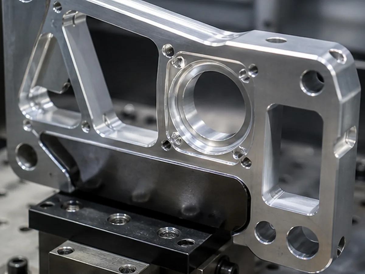
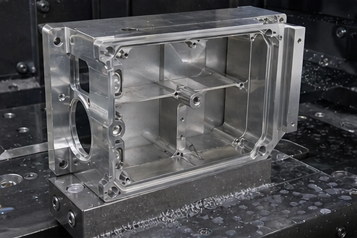
Formexi evaluates thin-wall housings, sleeves, brackets and structural components where clamping, cutting force, heat and residual stress can move the part. Wall thickness alone does not determine feasibility; wall height, unsupported span, material, stock and tolerance must be reviewed together.
Why Thin Parts Distort
- Residual stress is released as stock is removed.
- Clamping temporarily bends a flexible section.
- Cutting force deflects the wall away from the tool.
- Heat creates local expansion and measurement change.
- Finishing or heat treatment moves the completed geometry.
Screening Boundaries
Metal walls below approximately 0.5 mm and plastic walls below approximately 0.8 mm require specific review in the current provisional standards. These figures are not guaranteed minima. A short supported wall may be feasible where a tall unsupported wall is not.
Process Strategies
| Strategy | Purpose |
|---|---|
| Balanced roughing | Reduce uneven stress release. |
| Temporary ribs/tabs | Support the part during machining. |
| Soft or distributed clamping | Reduce local deformation. |
| Staged finishing | Allow movement before final dimensions. |
| Custom inspection support | Define free-state or assembled-state acceptance. |
Design Changes That May Help
Increase wall thickness locally, shorten unsupported spans, add ribs, use gradual transitions, relax nonfunctional tolerances or select a more stable stock form. The best option depends on weight, function and production quantity.
Inspection Condition
Define whether the part is measured free, restrained or assembled, and at what temperature. A flexible part can meet function in assembly while appearing out of tolerance in an unsupported inspection—or the reverse.
From CNC Machining for Thin-Wall Parts Requirements to a Controlled Manufacturing Plan
The purchasing issue behind CNC Machining for Thin-Wall Parts is that thin or flexible geometry can move during clamping, stock removal, heat treatment or measurement; as a result, a part may pass while restrained and fail after release or during assembly. Our response is to reviews stock condition, support points, cutting sequence, datum transfer and the free-state or restrained inspection condition before fixing the route. The objective is to protect assembly and validation schedules while reducing preventable scrap, rework and supplier-change risk.
For the CNC Machining for Thin-Wall Parts buying decision, before we confirm price or delivery, the buyer should send wall height and span, material condition, datums, functional tolerance, assembly support, finish sequence and measurement condition. If a requirement cannot yet be verified, we keep it as an open condition instead of presenting it as a guaranteed result.
Confirm the Process for CNC Machining for Thin-Wall Parts
For CNC Machining for Thin-Wall Parts, submit the 2D drawing and 3D model with matching revision, exact material and condition, quantity and repeat demand. Identify relevant datums, critical tolerances, GD&T, threads, difficult-access geometry, thin walls, roughness, heat treatment and finish requirements.
The route for CNC Machining for Thin-Wall Parts may require multiple setups, dedicated workholding, intermediate inspection or a justified secondary process. Select grinding, EDM, stress relief or post-finish verification only when the geometry and function require it; machine axis count alone does not establish final capability.
Show the Functional Support Conditions
Send wall map, datums, assembly constraints, material, stock form, finish and tolerance.