

Alignment Components
CNC Machining for Optical Mounts and Instrument Components
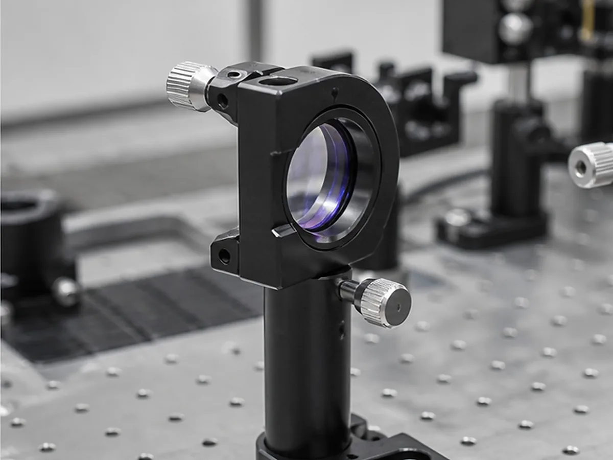
Formexi evaluates optical mounts, lens holders, instrument frames and alignment components where position, angular control, surface condition, stability and black finish may affect system performance. Optical performance itself requires customer design and system validation.
Typical Requirements
- Lens, mirror, sensor or detector mounting bores
- Threaded adjustment and retaining features
- Angular or positional relationships between optical axes
- Stable base and kinematic contact surfaces
- Low-reflectivity black finish and controlled handling
Datum and Stability
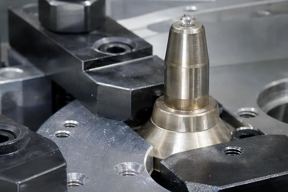
The drawing should connect optical interfaces to physical manufacturing datums. Thin aluminum structures may move after machining or anodizing. Temperature range and material expansion may also affect alignment beyond room-temperature inspection.
Threads, Bores and Surface Condition
| Feature | Review |
|---|---|
| Lens bore | Diameter, roundness, chamfer and retention method |
| Fine adjustment thread | Standard, fit, burrs, lubrication and functional gauge |
| Kinematic contact | Geometry, hardness and surface finish |
| Optical black surface | Reflectivity target, anodizing/coating and mask zones |
Cleanliness and Cosmetic Handling
General machining cleanliness is not cleanroom cleaning. If particle, residue, outgassing or optical-surface handling requirements apply, provide the exact standard and packaging method. Formexi does not claim cleanroom production until verified.
Inspection Boundary
Dimensional inspection can verify mechanical interfaces. Optical-axis performance, wavefront, stray light and calibrated system accuracy require specialized testing outside standard CNC inspection unless separately reviewed.
What Our Project Review Resolves Before Quoting CNC Machining for Optical Mounts and Instrument Components
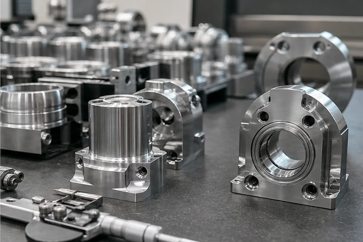
The purchasing issue behind CNC Machining for Optical Mounts and Instrument Components is that buyers can overpay or lose datum consistency when a process is chosen from a machine label instead of the part geometry; as a result, unnecessary setups or an unjustified high-end route can add cost without improving the functional result. Our response is to compares rotational versus prismatic geometry, feature access, datum relationships, workholding, batch size and measurement access before selecting milling, turning or a combined route. The objective is to protect assembly and validation schedules while reducing preventable scrap, rework and supplier-change risk.
For the CNC Machining for Optical Mounts and Instrument Components buying decision, before we confirm price or delivery, the buyer should send the 2D drawing and 3D model, overall size, material state, critical datums and tolerances, quantity, finish and inspection documents. If a requirement cannot yet be verified, we keep it as an open condition instead of presenting it as a guaranteed result.
Define the Project Controls for CNC Machining for Optical Mounts and Instrument Components
For CNC Machining for Optical Mounts and Instrument Components, state the part function and risk class, customer specifications, approved material and special-process sources, traceability level, change-control rules, record retention and nonconformance approval path. Add cleanliness, contamination, ESD, cosmetic, packaging or export restrictions where applicable.
Industry use does not by itself prove certification or suitability. Confirm the legal manufacturing entity, certification scope and project-specific documentation before supplier approval.
Separate Mechanical and Optical Requirements
Send optical interfaces, datums, temperature, finish, cleanliness and required test scope.