

Fluid-Control Components
CNC Machining for Hydraulic Manifolds
Formexi evaluates hydraulic manifolds with intersecting passages, threaded ports, sealing faces and controlled cleanliness requirements. Pressure rating and system safety remain the customer’s engineering responsibility unless a separate validated design-and-test scope is agreed.
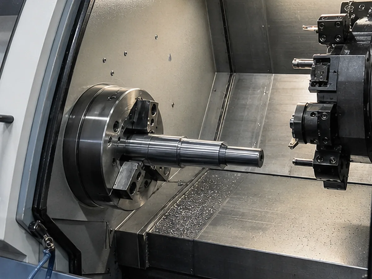
Manifold Features Requiring Control
| Feature | Risk |
|---|---|
| Intersecting drilled passages | Breakthrough position, burrs and trapped chips |
| Threaded ports | Standard, depth, orientation and sealing condition |
| Valve/cavity interfaces | Geometry, finish and proprietary specification |
| Plugged cross-holes | Seal method, inspection and leakage risk |
| Mounting/sealing face | Flatness, roughness and cleanliness |
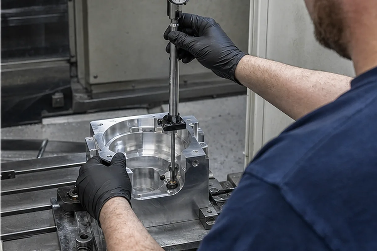
Materials
Aluminum is common where weight and machinability matter; steel or stainless may be considered for higher strength, temperature or corrosion requirements. Material approval must reflect fluid compatibility, pressure, environment and applicable system standard.
Deburring and Cleanliness
Internal burrs and chips can damage valves or contaminate a hydraulic system. The drawing should specify internal-edge requirements, flushing/cleaning, allowable contamination and packaging. “Deburr all edges” does not fully define inaccessible intersections.
Pressure and Leak Testing
Dimensional inspection does not prove pressure performance. If hydrostatic, pneumatic, leak or functional testing is required, provide pressure, medium, duration, allowable leakage, safety controls and report format. Formexi does not claim pressure-test capacity until the actual method and equipment are verified.
Documentation and Boundary
Material certificates, port gauges, cleanliness reports, pressure tests and traceability must be agreed before quotation. A machined manifold is not automatically certified for a hydraulic system merely because its dimensions meet the drawing.
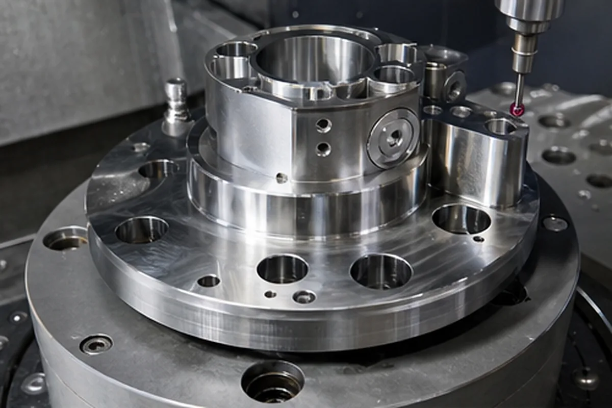
How We Control the Buyer Risk in CNC Machining for Hydraulic Manifolds
A useful supplier solution for CNC Machining for Hydraulic Manifolds starts when buyers can overpay or lose datum consistency when a process is chosen from a machine label instead of the part geometry. Because unnecessary setups or an unjustified high-end route can add cost without improving the functional result, our project review compares rotational versus prismatic geometry, feature access, datum relationships, workholding, batch size and measurement access before selecting milling, turning or a combined route. That approach helps the buyer avoid paying for the wrong process and lowers the chance of discovering a critical issue after machining or finishing.
For the CNC Machining for Hydraulic Manifolds buying decision, our review needs the 2D drawing and 3D model, overall size, material state, critical datums and tolerances, quantity, finish and inspection documents. We record assumptions, approval points and evidence requirements before the quotation becomes the production baseline.
Send the Fluid and Test Requirements
Provide passage drawing, port standard, pressure, fluid, cleanliness, plugs and inspection requirements.